
This guide provides detailed instructions for installing and operating SYT series rectifiers with capacities of 1000A and above. Follow these steps carefully to ensure safe and efficient operation of your equipment.
Installation Guide
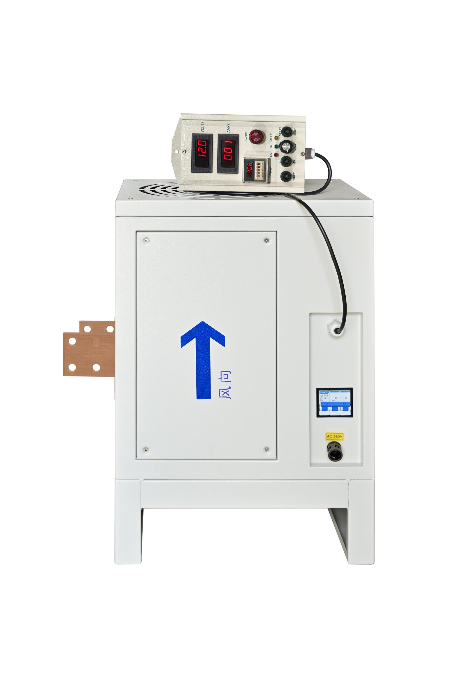
SYT Rectifier Installation Diagram
Installation Steps:
-
1 Open the rectifier side panel.
-
2 Connect the three-phase AC power lines from the outside of the rectifier's wiring port (it is recommended to use corrugated tubes to protect the power cables for better isolation of salt spray entering the rectifier through the power interface gaps).
-
3 Remove the rectifier power switch from its buckle.
-
4 Connect the three-phase wires to the three holes of the power switch in sequence (Note: After powering on, first test whether the rectifier fan is blowing outward - this indicates correct installation. If it is sucking inward, the wiring is incorrect and the rectifier switch wiring sequence needs to be adjusted until the airflow is outward).
-
5 After completing the power wiring, reinstall the rectifier power switch to its original buckle position and tighten it. Then close the outer panel and begin using the rectifier.
Installation Procedure Demonstration
Video: SYT Rectifier Installation Guide
Operation Guide
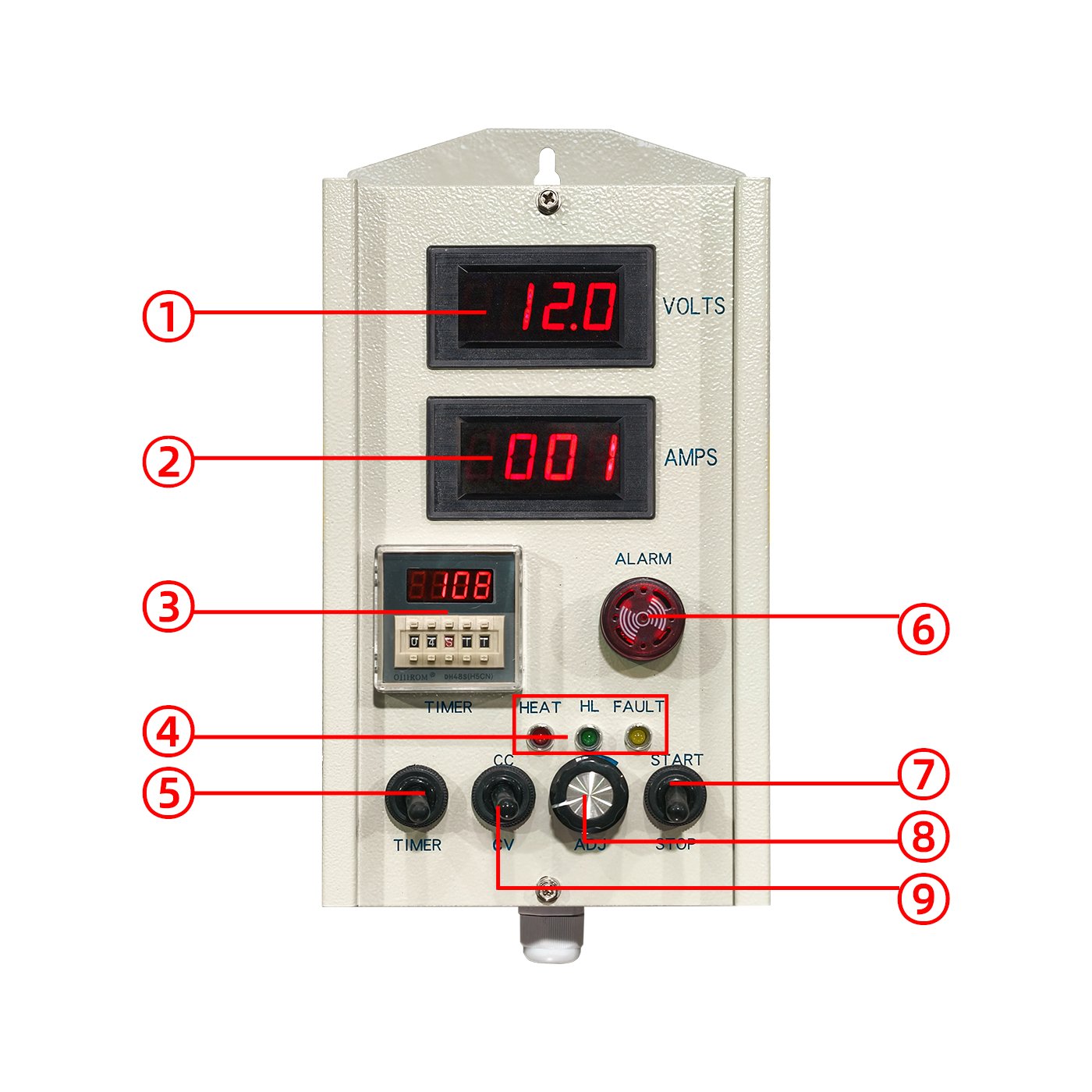
SYT Series Rectifier Control Panel
Operation Steps:
1. Power On/Off
- First, connect the rectifier power supply.
- Toggle the power switch upward to turn on the rectifier power.
- Toggle the power switch downward to turn off the rectifier power.
- The rectifier is started and stopped via the ⑦ "Start/Stop" switch.
- Toggle ⑦ upward to enter "Running" state (working indicator light ④ stays on).
- Toggle ⑦ downward to stop the rectifier.
- During operation, adjust current and voltage using adjustment knob ⑧ at any time.
2. Mode Selection
- Select "Constant Voltage (CV)" or "Constant Current (CC)" mode based on requirements.
- Toggle switch ⑨ downward to select "Constant Voltage (CV)" mode.
- Toggle switch ⑨ upward to select "Constant Current (CC)" mode.
3. Voltage/Current Adjustment
- Constant Voltage Mode: Rotate adjustment knob ⑧ - clockwise to increase voltage, counterclockwise to decrease voltage.
- Constant Current Mode: Rotate current adjustment knob ⑧ - clockwise to increase current, counterclockwise to decrease current.
Important Note:
Adjust slowly to ensure stable values. Stop adjusting once the target value is reached.
4. Timer Setting
- Toggle ⑤ upward on the control panel to activate the timer.
- Set working time using buttons on timer ③ (supports hours, minutes, seconds).
- For precise control, adjust in 1-second increments.
- Timer ③ automatically counts down when operation starts.
- When countdown reaches 0, alarm buzzer ⑥ red light illuminates with alarm sound.
- Device automatically stops output (current and voltage become 0).
- Keep ⑤ in downward position when timer is not in use.
Safety Reminder:
Ensure the rectifier is in the stopped state before turning off the power.
Operation Procedure Demonstration
Video: SYT Rectifier Operation Guide
Key Takeaways:
- Always verify fan direction after installation
- Select the correct mode (CV or CC) for your application
- Make adjustments slowly for stable performance
- Utilize timer functionality for automated operation
- Always stop rectifier before powering off