
This guide provides the complete factory parameter configuration procedure for the RS485 remote control panel of electroplating rectifiers, covering 21 parameter items including communication address, auto-compensation, counter settings, voltage/current calibration, communication protocols and protection modes.
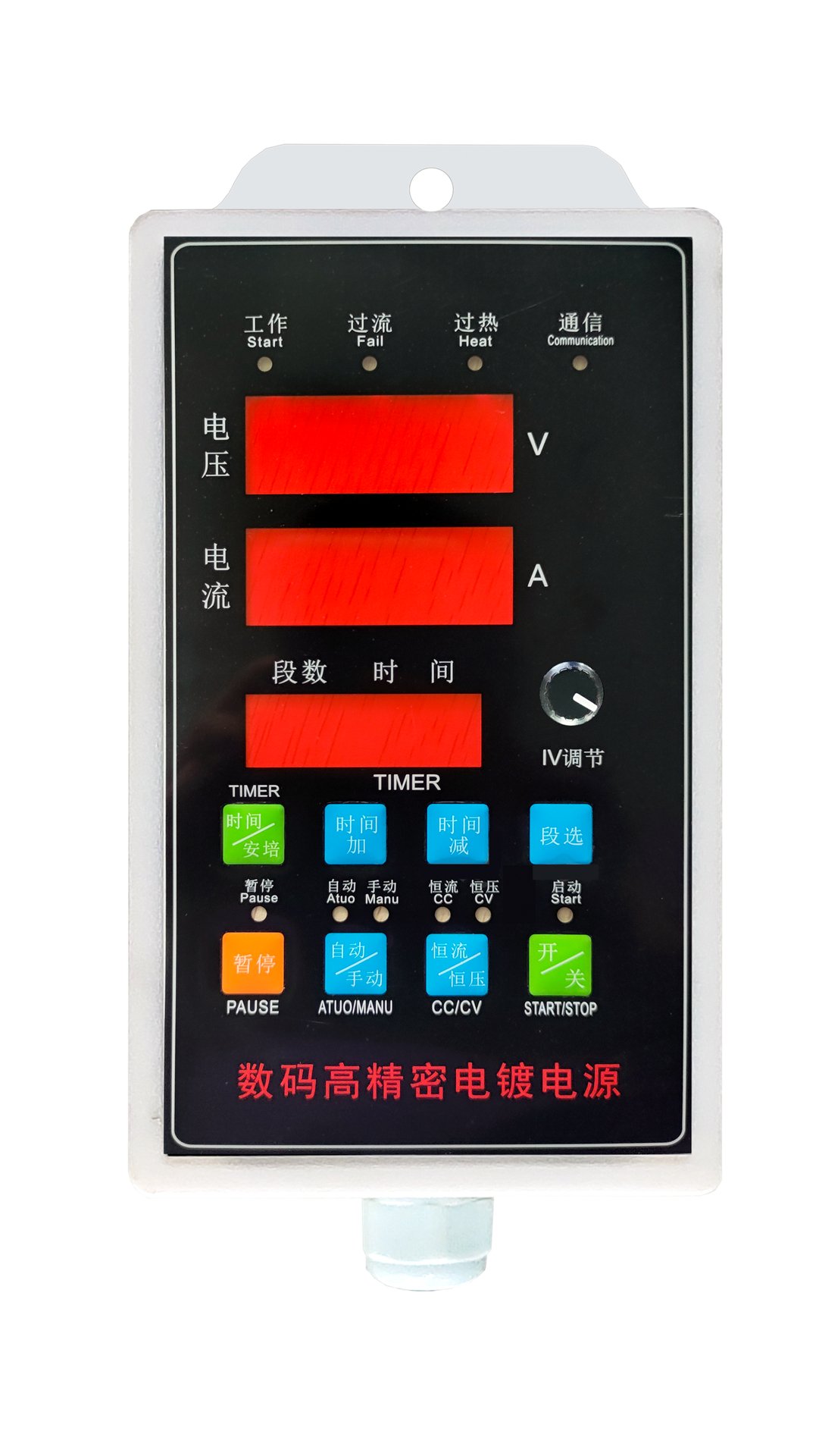
Factory Parameter Configuration Steps
1 Enter Configuration Mode
Power off the equipment, keep the START button pressed, and power on the equipment again.
2 Display Indication
The upper voltage digital display shows the configuration index number; the lower current digital display shows the configuration parameter value.
3 Switch Index Number
Use the Time-Up and Time-Down buttons to switch between index numbers.
4 Adjust Parameter Value
Adjust the corresponding parameter value via the pulse potentiometer.
5 Save and Lock
After configuration, press the Segment-Select switch button to save and lock the settings. The digital displays will show "----".
6 Activate New Parameters
Power off and power on the equipment again to activate the new parameters. Refer to the table below for detailed parameter descriptions.
Complete Parameter Table (21 Items)
| Index | Parameter Name | Configuration Value |
|---|---|---|
| 0001~32 | Power supply communication address | 0001 ~ 0032 (set communication address) |
| 01 | Auto power compensation selection | 00 = Auto compensation OFF (factory setting) 01-99 = Auto compensation ON; slow ramp time: 1-200 s 2 = Lock automatic mode (cannot select auto/manual mode) |
| 02 | Counter unit selection | 00 = 0.1 s 01 = 1 s 02 = 1 min 03 = 0.1 A·min 04 = 1 A·min 05 = 0.1 A·h 06 = 1 A·h |
| 03 | Counter operation mode | 01 = Power maintains original state when counter reaches zero; restart via start-stop switch 02 = Power maintains original state when counter reaches zero; restart via start-stop switch or workpiece removal 03 = Disables start button when counter reaches zero; restart via start-stop switch 04 = Current drops to 1/100 of max value when counter reaches zero; restart via start-stop switch or workpiece removal |
| 04 | Alarm time selection (0-99 s) | 0 ~ 99 (seconds) |
| 05 | Max voltage display setting | For 12V or lower equipment: set to 1200 (two decimal places) |
| 06 | Max voltage setting | Maximum output voltage of the equipment |
| 07 | Voltage decimal point selection | 0 = No decimal point 1 = One decimal place 2 = Two decimal places |
| 08 | Internal shunt rated current | Example: 200 A shunt configured as 2000 (one decimal place) |
| 09 | Max current setting | Maximum output current of the equipment |
| 10 | Current decimal point selection | Same rules as voltage decimal point setting |
| 11 | Pulse potentiometer type selection | 0 = Rotate left 1 = Rotate right |
| 12 | (Reserved / see item 11) | Refer to item 11 configuration |
| 13 | Current reduction percentage | 0 ~ 50 (%) |
| 14 | Operating segment number selection | 1 ~ 20 |
| 15 | External counter unit selection | 1 → A·min 60 → A·h |
| 16 | Communication mode selection | 0 = Modbus RTU 1 = Internal checksum protocol (for old management boards without touch screen) 2 = Internal CRC verification protocol (for new-generation touch screen management boards) 3 = Hard anodizing communication protocol (for Oct-2017 touch screen version) |
| 17 | Protection / protocol selection | 0 = Normal overcurrent / over-temperature protection 1 = Switch overcurrent / over-temperature protection 4 = Liyuan protocol, positive start-stop logic 5 = Liyuan protocol, reverse start-stop logic |
| 18 | Parity bit selection | 0 = No parity 1 = Odd parity 2 = Even parity |
| 19 | Overvoltage protection limit | 0 = Rated voltage limit; 0 disables protection |
| 20 | Switching transition time | Unit: 0.1 s; 0 = Switching function disabled |
| 21 | Cyclic timer selection | 0 = No cycle 1 = Cycle activated (modifies items 3 and 4) |