
Overview
Chemical liquid filters undertake the core task of liquid purification in electroplating, chemical industry, PCB manufacturing and other industries. Proper installation and piping not only determine filtration performance, but also directly affect equipment service life and operational safety. The key considerations during installation and piping are listed as follows:
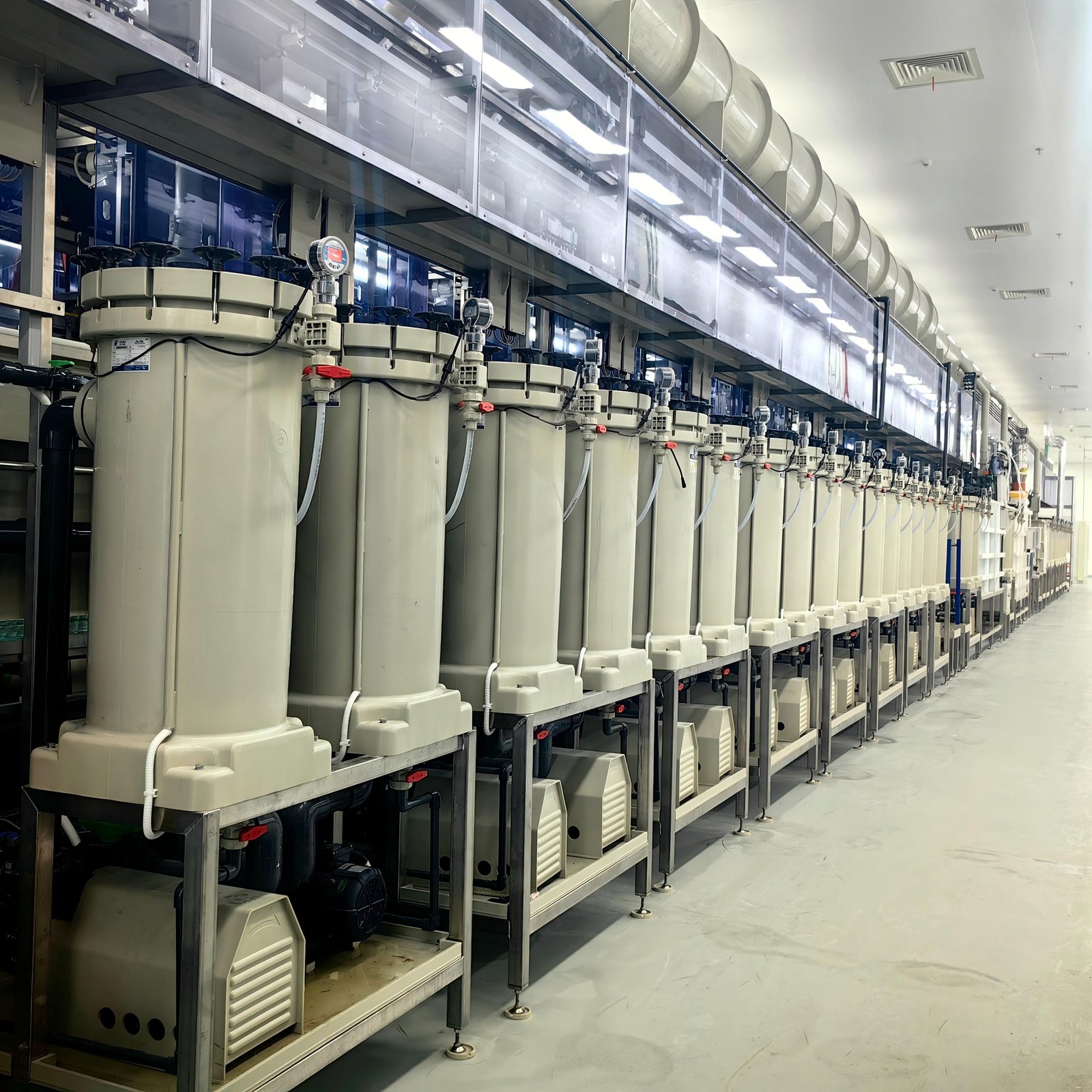
1. Selection of Installation Location
- The filter shall be placed on a flat, solid ground without direct sunlight or heat radiation, with good surrounding ventilation to facilitate future maintenance and inspection.
- Locate the unit as close to the chemical tank as possible to shorten pipeline length and reduce frictional resistance loss.
- Comply with the pump's suction lift limit: the centerline of the filter inlet shall generally be lower than the minimum liquid level of the tank to guarantee smooth self-priming.
2. Connection of Inlet and Outlet Pipelines
Inlet pipeline (critical part)
- Pipes should be short and straight, with no more than 2 elbows to minimize suction resistance.
- All joints must be tightly sealed; tiny air leakage will lead to poor priming or unstable flow rate.
- A foot valve or filter screen is recommended at the inlet to prevent foreign particles from entering the pump body.
Outlet pipeline
- Top outlet or bottom outlet can be adopted according to process requirements.
- If flow regulation is needed, install a regulating valve on the outlet pipeline, with a buffer pipe section reserved upstream of the valve.
- For high-temperature chemical liquids, heat-resistant piping materials shall be used, and thermal expansion compensation shall be taken into account.
3. Selection of Pipe Diameter & Material
- The inner diameter of pipelines shall not be smaller than the filter’s inlet/outlet diameter; excessively thin pipes will raise flow resistance and cause flow loss.
- Pipe material must be compatible with the chemical liquid:
- Ordinary acid & alkali liquid: UPVC / CPVC pipes
- Strong oxidizing media: PVDF / PPH pipes
- Organic solvents: fluoroplastic or stainless steel pipes
- Never select inferior materials to cut costs, to avoid pipeline corrosion and leakage.
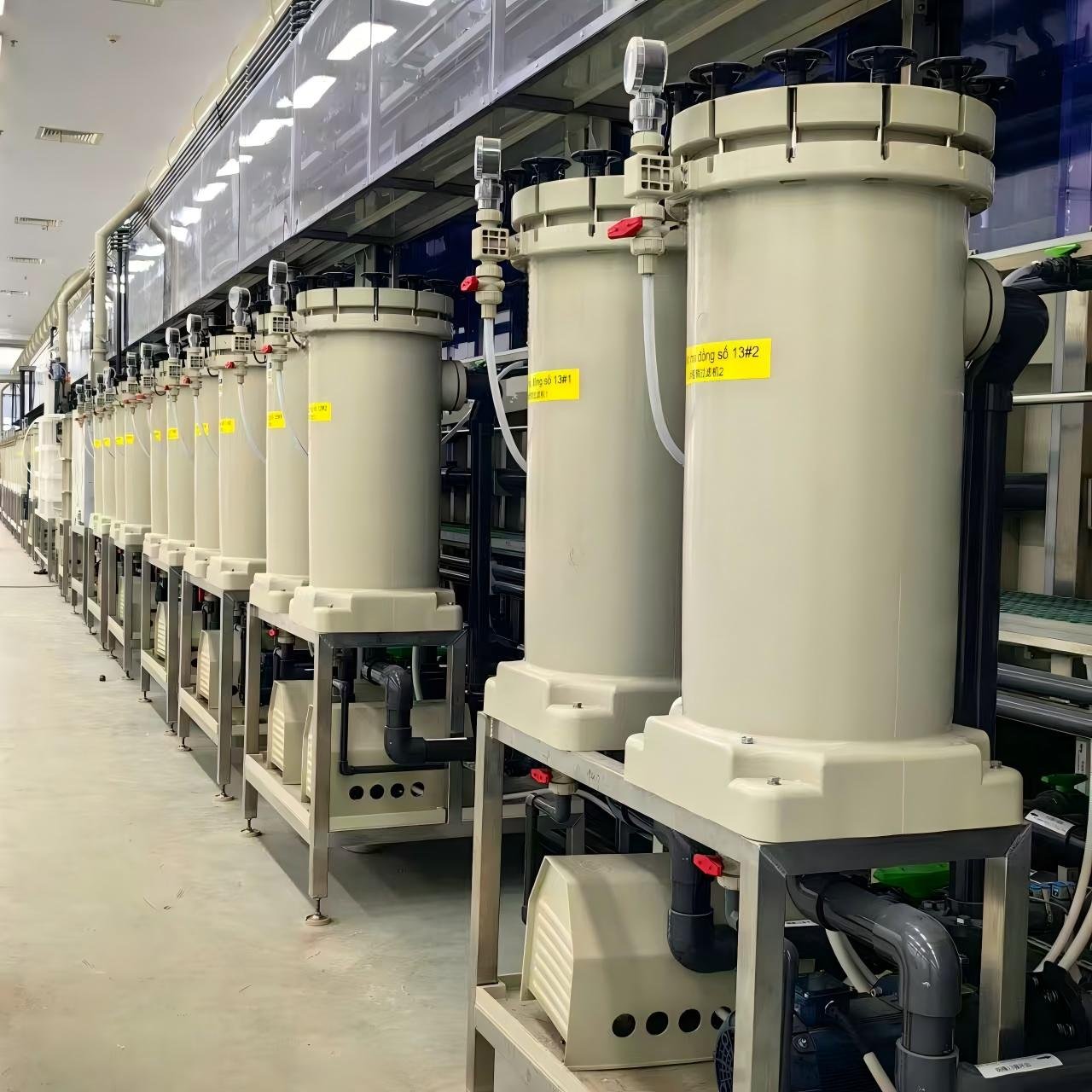
4. Configuration of Valves & Instruments
- Install a ball valve at the filter inlet to cut off liquid supply for disassembly and maintenance.
- Fit a regulating valve or butterfly valve at the outlet to adjust flow and pressure.
- A pressure gauge is suggested on the outlet pipeline; filter clogging can be judged by monitoring pressure fluctuation.
- For long pipelines or high-lift delivery, install an air vent valve at the highest point to avoid air binding.
5. Drain & Bypass Design
- Fit drain valves at pipeline low points to empty residual liquid during filter cleaning or filter element replacement.
- For high-flow systems, a bypass recirculation pipe can be arranged to return partial liquid to the original tank. It facilitates flow adjustment and enables continuous liquid supply to the main system while replacing filter elements.
6. Post-installation Inspection Checklist
Conduct tightness test for all pipelines: flush with clean water first to check all joints for leakage; switch to chemical liquid operation only after no leak is confirmed.
Startup sequence: Open the inlet valve fully first, ensure the pump chamber is fully filled with liquid before starting the motor, then slowly open the outlet valve to adjust to target flow rate.
Conclusion: Standardized installation and piping enable chemical liquid filters to operate at full efficiency, extend the service life of filter elements and pump bodies, and guarantee safety for operators and the production environment.