
Selecting the right electroplating power supply is the foundation for stable production, consistent coating quality and improved efficiency. This guide covers six key dimensions: structure type, process requirements, rated output voltage, rated output current, working efficiency and cooling methods.
1 Structure Type
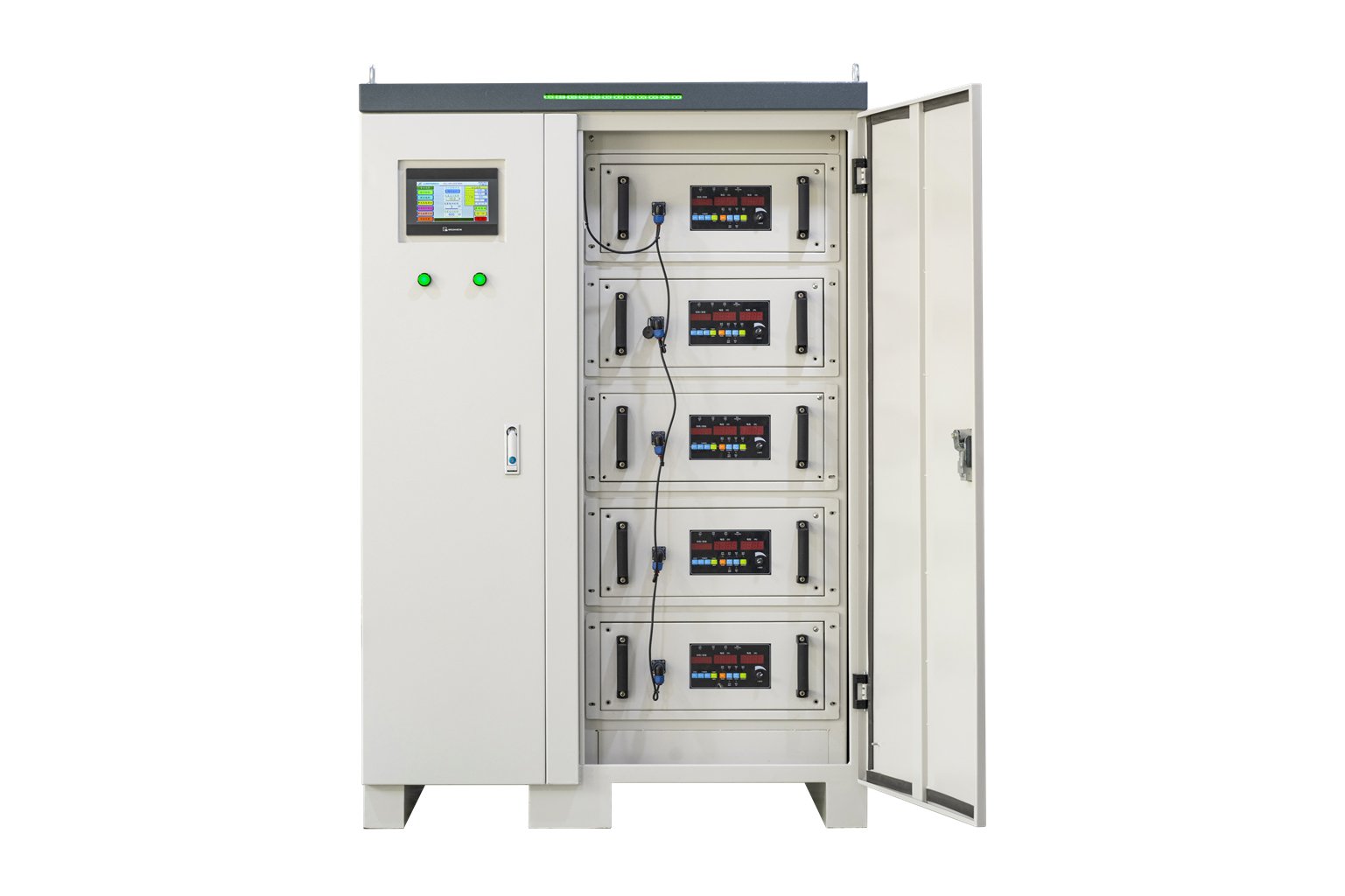
Electroplating power supplies are divided into cabinet type and anti-corrosion type. The structural selection shall be comprehensively determined by the corrosion level of the electroplating workshop, ventilation system, plating tank layout and other on-site conditions. With the popularization of clean electroplating production, most factories separate power supplies from plating tanks in different rooms. For such cases, cabinet-type power supplies with remote control function are recommended.
For anti-corrosion power supplies, main electrical components are isolated from corrosive gas by medium (e.g. transformer oil) or sealed to mitigate corrosion. Compared with cabinet-type power supplies, anti-corrosion models feature larger size and higher cost, yet with stronger adaptability to harsh environments.
2 Electroplating Process Requirements
For general electroplating processes: rectifiers below 3kW can adopt single-phase input power; for capacity above 3kW, three-phase input power is required to avoid grid imbalance.
Special electroplating processes with strict ripple coefficient requirements (such as hard chrome plating and hard anodizing) demand high waveform continuity. Regulator-type silicon rectifiers or thyristor rectifiers equipped with filters are preferred; pulse power supplies are also widely adopted for hard anodizing.
Some special electroplating processes require customized output waveforms: single polarity reversal, periodic polarity reversal, single pulse, bipolar pulse, DC superimposed pulse, DC superimposed AC and multi-section composite waveforms. Different waveforms serve different applications. Manufacturers classify models based on output waveforms and usage, so you can select the power supply according to the required waveform.
3 Rated Output Voltage
Rated output voltage refers to the maximum DC voltage that the power supply can steadily deliver within allowable grid fluctuation and load range.
Undervoltage will fail to meet process requirements. Excessively high voltage wastes rectifier capacity and reduces efficiency. For thyristor and high-frequency switching power supplies, excessive voltage margin increases ripple coefficient and impairs coating quality.
Standard rated voltage options:
4 Rated Output Current
Rated output current is the maximum current that the power supply can continuously and stably output under normal working conditions. Calculate the required maximum current according to tank size, bath concentration, temperature, anode & cathode area, current density and production capacity. Reserve an extra 10%~20% operating margin on top of basic process demand.
Standard rated current options:
5 Working Efficiency
Working efficiency = DC output power / AC input power. Efficiency reflects internal power loss.
Electroplating power supplies have evolved from silicon rectifier, thyristor rectifier to high-frequency switching power supply, with the trend of higher efficiency and lower loss. On the premise of meeting process specifications, high-efficiency and energy-saving power supplies are preferred.
6 Cooling Methods
Four cooling options are available according to capacity, power semiconductor type and ambient conditions (the ranges below are empirical references instead of rigid limits):
| Cooling Type | Typical Capacity Range | Application Note |
|---|---|---|
| Natural Cooling | 50 ~ 300A | For small units |
| Forced Air Cooling | 200 ~ 5000A | For medium & small units |
| Water Cooling | ≥ 5000A | Commonly used for large units; optional for some medium-high power models |
| Oil Cooling | Medium & small units | For corrosive environment |
Combined cooling (air/water/oil mixed cooling) can be adopted in certain scenarios for better heat dissipation.